
When installing or rebuilding a differential, getting the tooth contact pattern right is just as critical as setting the correct backlash. A misread or ignored contact pattern is one of the leading causes of gear noise, premature wear, and differential failure — even when backlash measurements appear within spec.
This guide explains how to perform a gear contact test on crown wheel and pinion gears, how to interpret each pattern type, and what corrective actions to take. Whether you’re a workshop technician or a fleet maintenance engineer, understanding these patterns will help you avoid costly mistakes during setup.
Step 1: How to Perform the Gear Contact Test
Once backlash has been set to the correct specification, the next step is to verify the tooth contact pattern between the crown wheel and pinion. This check confirms that the gears are properly aligned under load conditions — backlash alone does not guarantee correct gear engagement.
What you’ll need:
- Gear marking compound (such as Prussian blue or engineer’s blue paste)
- A clean cloth or brush for application
- A wrench or holding tool to apply resistance to the crown wheel
Procedure:
- Apply a thin, even layer of marking compound to approximately six teeth on three evenly spaced sections around the crown wheel — covering both the drive side and coast side of the tooth profiles.
- Hold the crown wheel to create resistance, then rotate the pinion several turns in both directions. This simulates load and transfers the compound to show actual contact zones.
- Carefully examine the contact impression left on the teeth and compare it against the reference patterns below.
Important: Always check the pattern on both the drive side (power delivery) and the coast side (engine braking). They may differ and both need to be within acceptable range.
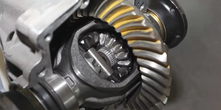
Understanding Crown Wheel and Pinion Tooth Structure
Understanding tooth contact marks (Fig. (a-f)) If the crown wheel to pinion tooth contact pattern is incorrect, there are two adjustments that can be made to change the position of tooth contact. These adjustments are of backlash and pinion depth.

Step 2: How to Read and Interpret Each Contact Pattern
The contact pattern tells you two things: where the gears are making contact along the tooth length (toe to heel), and where they are making contact across the tooth height (face to flank). Each of these dimensions is controlled by a different adjustment.
- Toe-to-heel position is controlled by backlash (moving the crown wheel closer to or further from the pinion)
- Face-to-flank position is controlled by pinion depth (how deep the pinion sits in relation to the crown wheel)
Use the pattern reference guide below to identify your current contact condition and determine the correct corrective action.

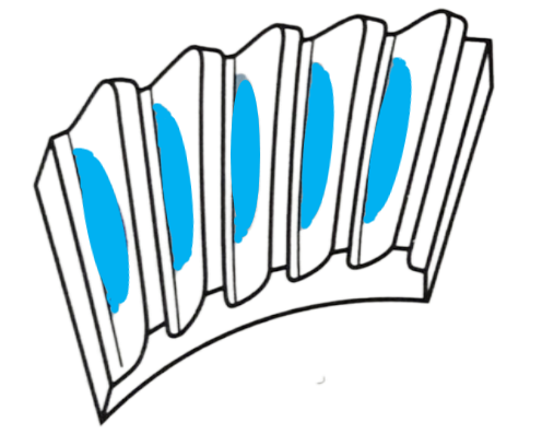
Optimal Contact: pattern is concentrated in the center of the drive gear tooth.

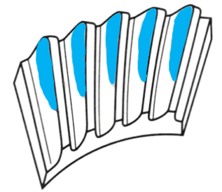
Heavy Heel Contact
What you see: The contact patch is concentrated at the large end (heel) of the crown wheel tooth.
What it means: Backlash is too large — the crown wheel is sitting too far away from the pinion.
How to fix it:
- Move the crown wheel closer to the pinion by adding shims to the crown wheel side of the differential carrier and removing an equal thickness from the opposite side.
- Alternatively, tighten the crown wheel side adjuster nut while loosening the opposite side nut by the same amount.
- If backlash drops below the minimum specified after adjustment, fit a thinner shim (washer) behind the pinion head to bring it back within range.
Low Contact

Toe Contact
Heel Contact
Final drive axle noise and defects
Gear-related noise is often the first sign of an incorrect contact pattern or improper differential setup. For a detailed breakdown of differential noise types and what each sound indicates, see our guide:

Why Your LSD Is Making Noise
Why is your limited slip differential making noise? Learn the real causes of LSD chatter, clunking, and whining—plus proven fixes and prevention tips.
Incorrect meshing of crown wheel and pinion teeth
- Abnormal noises produced by poorly meshed teeth generate a very pronounced cyclic pitch whine in the speed range at which it occurs whilst the vehicle is operating on either drive or overrun conditions.
- Noise on drive If a harsh cyclic pitch noise is heard when the engine is driving the transmission it indicates that the pinion needs to be moved slightly out of mesh.
- Noise on overrun If a pronounced humming noise is heard when the vehicle’s transmission overruns the engine, this indicates that the pinion needs to be moved further into mesh.
- Slackness in the drive A pronounced time lag in taking the drive up accompanied by a knock when either accelerating or decelerating may be traced to end play in the pinion assembly due possibly to defective bearings or incorrectly set up bearing spacer and shim pack.
- Bearing noise Bearings which are defective produce a rough growling sound that is approximately constant in volume over a narrow speed range. Driving the vehicle on a smooth road and listening for rough transmission sounds is the best method of identifying bearing failure.
- A distinction between defective pinion bearings or differential cage bearings can be made by listening for any constant rough sound. A fast frequency growl indicates a failed pinion bearing, while a much slower repetition growl points to a defective differential bearing. The difference in sound is because the pinion revolves at about four times the speed of the differential assembly.
- To distinguish between differential bearing and half shaft bearing defects, drive the vehicle on a smooth road and turn the steering sharply right and left. If the half shaft bearings are at fault, the increased axle load imposed on the bearing will cause a rise in the noise level, conversely if there is no change in the abnormal rough sound the differential bearings should be suspect.
Defective differential planet and sun gears
Not Sure About Your Contact Pattern? Send Us a Photo.
Interpreting tooth contact patterns correctly requires experience — and an incorrect diagnosis can lead to repeated failures. If you’re unsure what your pattern is telling you, our engineering team is happy to help.
Send us:
- A clear photo of your crown wheel contact pattern (drive side and coast side)
- Your current backlash measurement
- Basic application details (vehicle model, gear ratio, operating conditions)
We’ll review your setup and advise whether adjustment is sufficient or whether a replacement crown wheel and pinion set is needed.
